

This project has received funding from the Fuel Cells and Hydrogen 2 Joint Undertaking (now Clean Hydrogen Partnership) under Grant Agreement No 826247. This Joint Undertaking receives support from the European Union’s Horizon 2020 Research and Innovation programme, Hydrogen Europe and Hydrogen Europe Research.
Document description
Document name D3.4 Main results of the hydrogen fuel system
Date 30/09/2022
Submission Date 31/10/2022
Responsible organization H2F, ALAT
Author(s) Rouaid Al-Taie (H2FLY), Loïc Jeunesse (ALAT)
Co-Author(s) Maria Sol Rau (H2FLY)
Reviewers Gubaz Aptsiauri (H2FLY), Carsten Giersberg (H2FLY), Denis Favier (ALAT)
Table of Contents
Document description
1. EXECUTIVE SUMMARY
2 Introduction
2.1 General Introduction
2.2 Purpose and scope of this deliverable
3 Hydrogen Fuel System (HFS)
3.1 Introduction to HFS
3.2 HFS design and manufacturing for HEAVEN
4 Cryogenic System
4.1 Introduction to cryogenic system
4.2 Design of the cryogenic system for HEAVEN
4.3 Manufacture of the cryogenic system in HEAVEN
4.4 Control/command of the cryogenic system
4.5 Tests of the cryogenic system
5 Ground Support Equipment (GSE)
5.1 Definition of the ground support equipment
5.2 GSE for HEAVEN
6 Cryogenic hydrogen safety
6.1 Introduction to cryogenic hydrogen safety
6.2 Cryogenic hydrogen safety to implement in HEAVEN
Conclusion
List of Figures
Figure 1: Cryogenic Tank
Figure 2: Process Diagram of the tank
Figure 3: Inner tank
Figure 4: Valve box
Figure 5: End of tank manufacturing
Figure 6: LH2 tank and its flight controller
Figure 7: LH2 tank on vibration test bench
Figure 8: GSE overview
Figure 9: GSE
Abbreviations
FC Fuel Cell
ALAT Air liquide advanced technologies
LH2 Liquid Hydrogen
RH Right Hand
GSE Ground support Equipment
HFS Hydrogen Fuel System
1 EXECUTIVE SUMMARY
HEAVEN objective is to address the gap between research and product stage of a zero-emission fuel cell (FC) based propulsion technology to achieve emission and noise reduction scenarios and meet the environmental goals for aviation towards the year 2050.
HEAVEN cryogenic hydrogen storage technology was transferred from automotive and space technology to aircraft application. The information disclosed in this document is non-confidential and was generated in cooperation between ALAT and H2FLY.
The joint effort of the partners is the key to successfully develop and integrate the Hydrogen Fuel System (HFS) in the HY4 aircraft, which is property of H2FLY.
After the integration of the hydrogen fuel system in the HY4, the first ground tests are scheduled to start in 2023. It is expected that this modification doubles the range of the HY4.
2 Introduction
2.1 General Introduction
In the development of the hydrogen fuel system for aircraft application, and specifically for the HY4, the following actions were implemented:
- Design and Manufacture of the HFS
- Design and Manufacture of the LH2 System (cryogenic system)
- Definition of HFS control and monitoring measures
- Preparation of Ground Support Equipment
- Analysis of cryogenic hydrogen safety conditions and measures
- Quality Evaluation of the different parts
A description of the result of the implementation is presented in the coming sections.
2.2 Purpose and scope of this deliverable
The purpose of this deliverable is to:
- Present the main cooperation results of this project
- Present the steps followed to develop the HFS for HEAVEN
- Leave the first evidence on the use of liquid hydrogen in aviation
- Share knowledge for further developments
3 Hydrogen Fuel System (HFS)
3.1 Introduction to HFS
Liquid hydrogen has the advantage that it has a significantly higher gravimetric and volumetric energy density than a compressed gaseous hydrogen tank system. But for the hydrogen to remain liquid, it must be cooled to at least 253 degrees Celcius below zero. To feed fuel cells operating at >40°C, H2 is heated up, in a HFS specially designed for flying operations. An aircraft that uses liquid hydrogen has the potential to transform the way we travel delivering true zero-emissions.
HEAVEN project proposes to develop a new hydrogen fuel system based on cryogenic technology for aircraft applications. This technology is supported by the extended experience of ALAT (in producing hydrogen cryogenic tanks for different applications) and H2Fly (in hydrogen aircraft and hydrogen aviation)
In HEAVEN the Hydrogen Fuel System (HFS) includes:
- A cryogenic system
- A hydrogen gaseous buffer tank
- Ground Support Equipment (GSE)
- A control command module
- Hydrogen heating system
- Safety system
This configuration of the HFS was designed to:
- decrease the cryogenic system criticality
- to minimize redundancies on the cryogenic system,
- lead to less complexity and
- reduce risks in the project
HEAVEN-partners developed a system that ensure maximum reliability and safety for the novel aircraft hydrogen HY4.
3.2 HFS design and manufacturing for HEAVEN
For the design and manufacturing of the HFS, the buffer tank architecture has been designed and the components for coupling the buffer tank with the LH2 tank have been specified and procured. With this architecture it is possible to operate the aircraft with different tank modes, which includes the supply of hydrogen to the fuel cells from buffer tanks alone, from cryogenic tank or in hybrid mode when all tanks are supplying to the fuel cells. This feature is mainly needed for safety purposes to get a high level of redundancy in the event of a failure of one tank. Since the cyrogenic tank can supply the fuel cells independently from the buffer tank, it is possible to test the capabilities and the limits of the LH2 system in flight.
4 Cryogenic System
4.1 Introduction to cryogenic system
As mentioned in section 3.1, a cryogenic tank has been developed and manufactured to power the aircraft HY4.
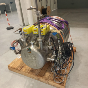
Figure 1 Cryogenic tank
4.2 Design of the cryogenic system for HEAVEN
A cryogenic Hydrogen tank should be considered as a “system” with the main functions described hereafter.
The process diagram on the below picture shows the main components and consists of:
- An inner and an outer tank, with vacuum in between to allow very limited thermal entries, which is necessary to keep LH2 at -253°C.
- Several cryogenic valves for fueling and withdrawal purposes, and one isolation valve before the fuel cell circuit.
- A heat exchanger to increase LH2 temperature from -252°C to more than 0°C.
- An internal heater to increase LH2 pressure before flight and to maintain it in flight.
- One boil-off valve to evacuate boil-off if needed
- One pressure safety valve and two burst disc to manage failure cases such as loss of vacuum or external fire.
- Relevant instrumentation to manage the system and safety scenarios.
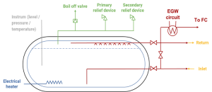
Figure 2 Process Diagram of the tank
The key performances of the LH2 tank are the following:
- The tank supply H2 at 6.3 barA for the fuel cell.
- 15kg of LH2 are stored in the tank and its mass is 140kg including LH2, leading to a gravimetric index around 11.5%.
- The tank can feed up to a 150kW fuel cell.
- Tank dormancy time (time between filling and boil-off valve opening) is between 10 and 15h..
Note that the gravimetric index may seem rather low, but almost half of the mass of the tank is constituted by the valves box and all its components, which shall remain the same independent of the size of the tank. For instance, a 3-fold larger tank (so as to store 50 kg of LH2) would feature a 18% index. The larger the tank the better the index.
4.3 Manufacture of the cryogenic system in HEAVEN
The manufacturing of the cryogenic tank has been finalized. The main steps are described above:
Inner tank manufacturing, insulation and integration in the outer tank
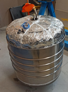
Figure 3 inner tank
Valve box manufacturing
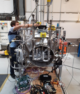
Figure 4 Valve box
Tank at end of manufacturing
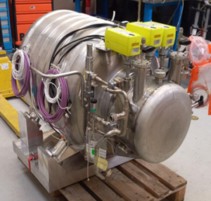
Figure 5 End of tank manufacturing
4.4 Control/command of the cryogenic system
A dedicated control/command system has been developed for the LH2 tank. It is a fully automatic system allowing to maintain a constant pressure in the tank during the flight. In addition, alarm and fluid level are returned to the pilot and all safety function are analogic to improve reliability.
The control/command dialogs with:
- The controller of the refueling station during filling.
- The aircraft in flight.
4.5 Tests of the cryogenic system
Several tests have been performed on the LH2 tank:
- Functional tests with liquid hydrogen: All the normal, degraded and safety functions was tested together with the flight controller developed for the tank.
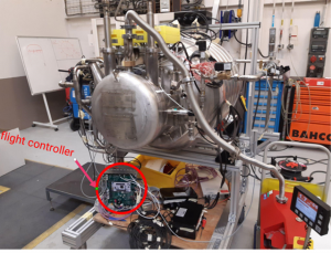
Figure 6 LH2 tank and its flight controller
- Vibration tests with liquid nitrogen: tests was performed according to DO160 with 16kg liquid nitrogen in the tank to represent the maximal mass that can be stored in the tank.
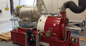
Figure 7 LH2 tank on vibration test bench
5 Ground Support Equipment (GSE)
5.1 Definition of the ground support equipment
The ground support equipment is the equipment allowing to fill the cryogenic tank on ground.
5.2 GSE for HEAVEN
The picture below shows an overview of the whole system allowing to fill the tank on the airport:
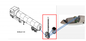
Figure 8 GSE overview
The picture below shows more in details what the GSE looks like:
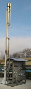
Figure 9 GSE
Basically, the GSE consists of a valve box that make the interface between a LH2 trailer and the aircraft. There is also a vent line allowing to vent the boil-off gas and then return gas during filling to a safe location and power supply for the electrical heater and for the valves.
6 Cryogenic hydrogen safety
6.1 Introduction to cryogenic hydrogen safety
All safety analyses have been performed according to ARP4761 guidelines in all flight phases.
6.2 Cryogenic hydrogen safety to implement in HEAVEN
When combining all operational modes with all possible failure cases, we end up with more than 250 failures scenarios that have been thoroughly analyzed together with mitigation actions.
Out of that, a few of them are hazardous or catastrophic.
To reach an acceptable situation, mitigation barriers have been developed and failure tree analysis has been made. The conclusion is that the cryogenic tank is safe and can be used to power the HY4 aircraft
Conclusion
This report provides a summary on the design and development of a new hydrogen fuel system based on cryogenic technology for aircraft applications. The technology will be used within the HEAVEN project framework to enable the HY4 aircraft to reach longer distances.
This endeavour was supported by:
- ALAT extended experience in producing hydrogen cryogenic tanks for different applications
- H2FLY knowledge on hydrogen fuel cell technology and experience in the development of hydrogen-electric propulsion systems for aircraft.
The HFS consist of six main parts: the cryogenic system, the buffer tank, the ground support equipment, the control command module, the hydrogen heating system and safety system. Each part of the HFS was designed and tested following aircraft norms and specifications.
This innovative system was developed to power the aircraft HY4 under the highest safety and reliability conditions. After the rigorous functionality evaluation, the HFS integration has started and will be completed in the coming months.